How to use the ERP connector
Custom Design creation and Event Mapping
-
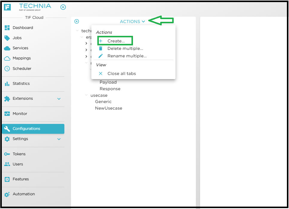
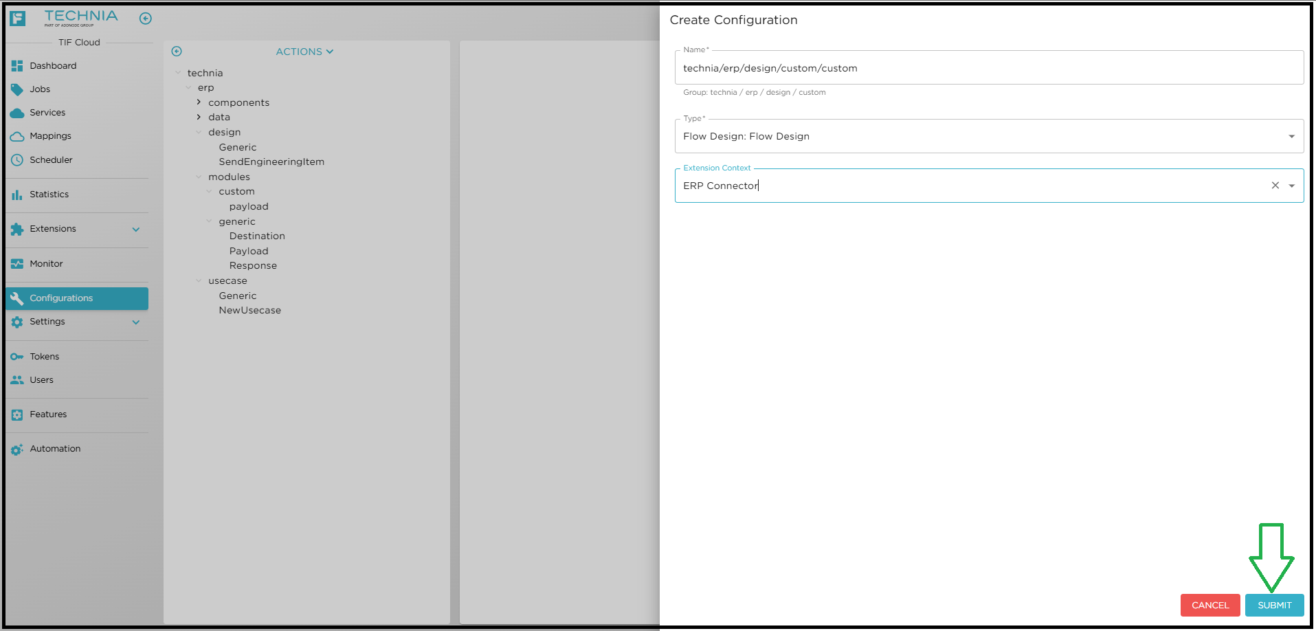
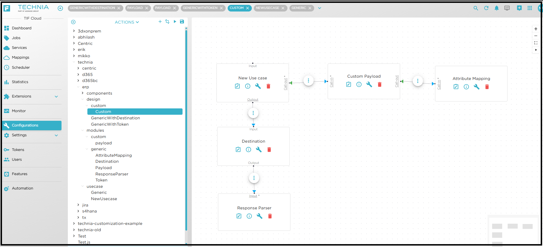
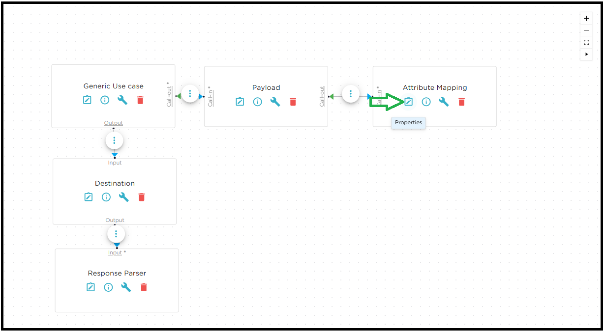
Generate design like Generic and replace the payload module with yours. Associate this custom design with event mapping. For additional information about event mapping, refer to EVENT MAPPING.
-
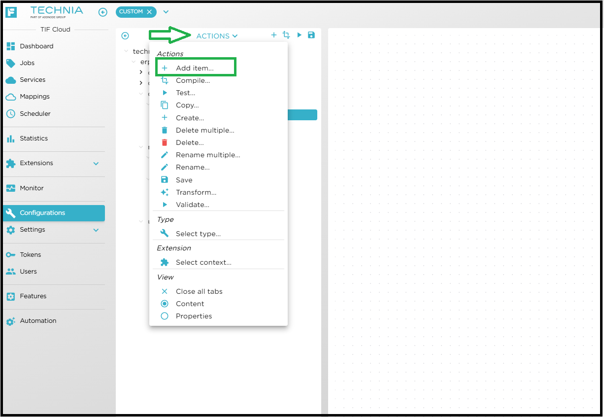
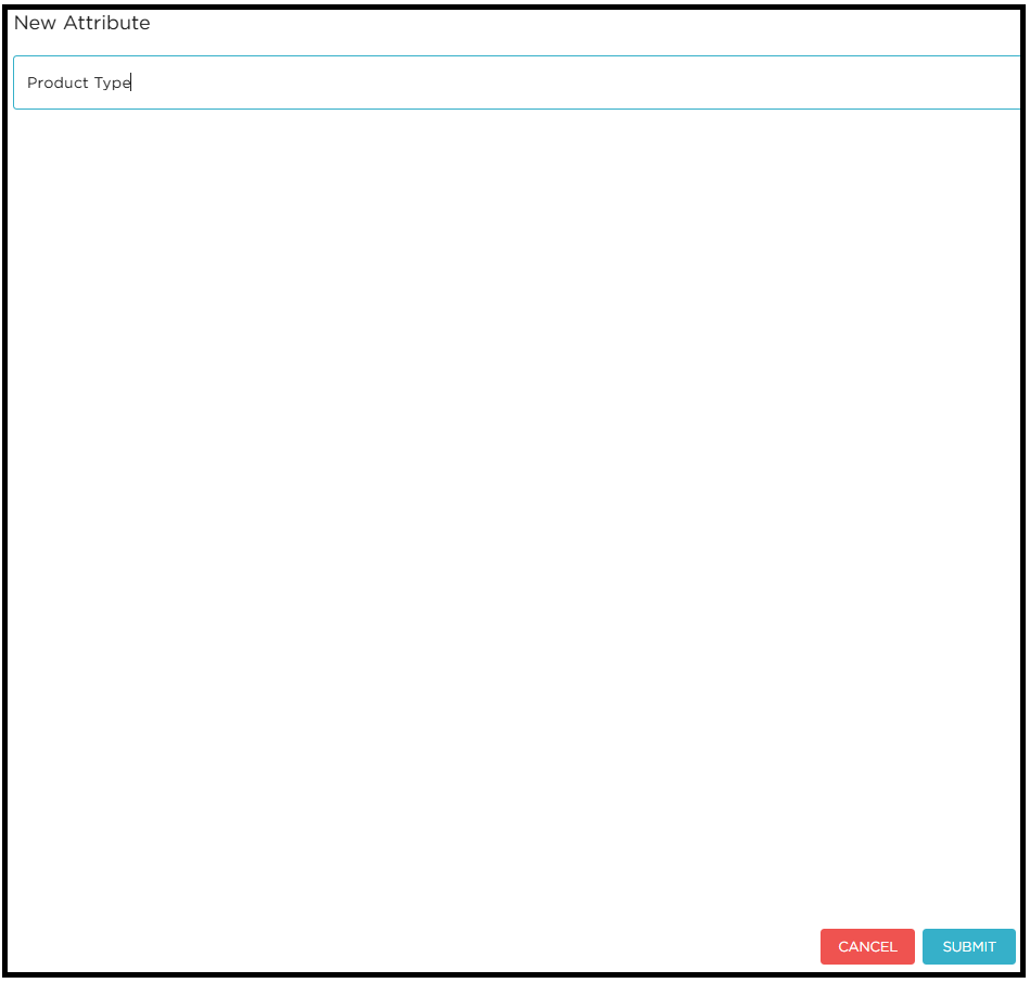
Add or modify the metadata to the module as per requirement.
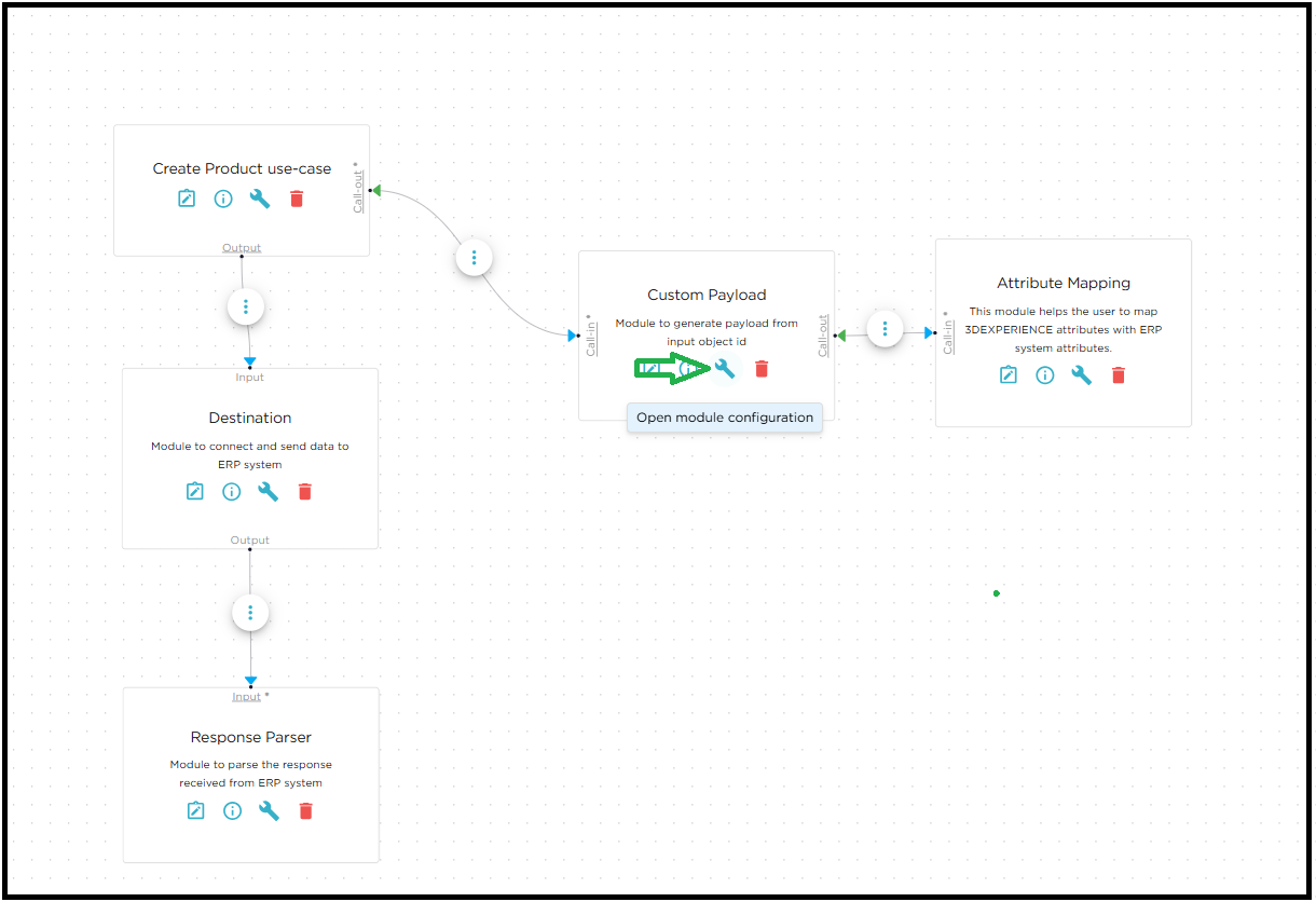
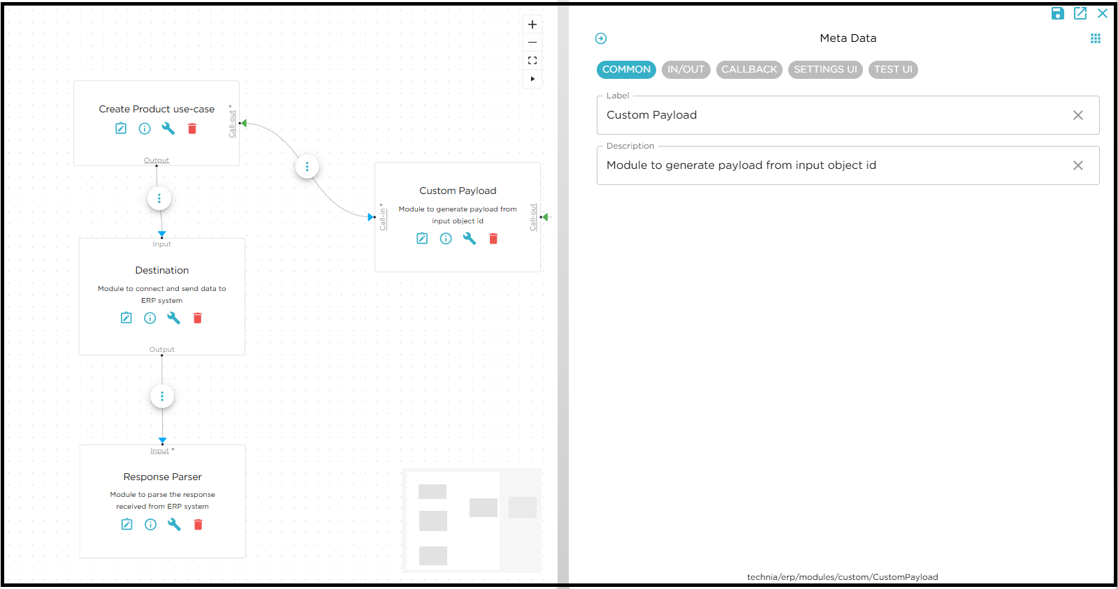
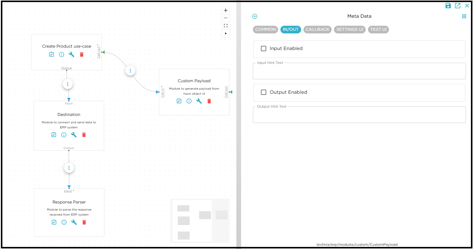
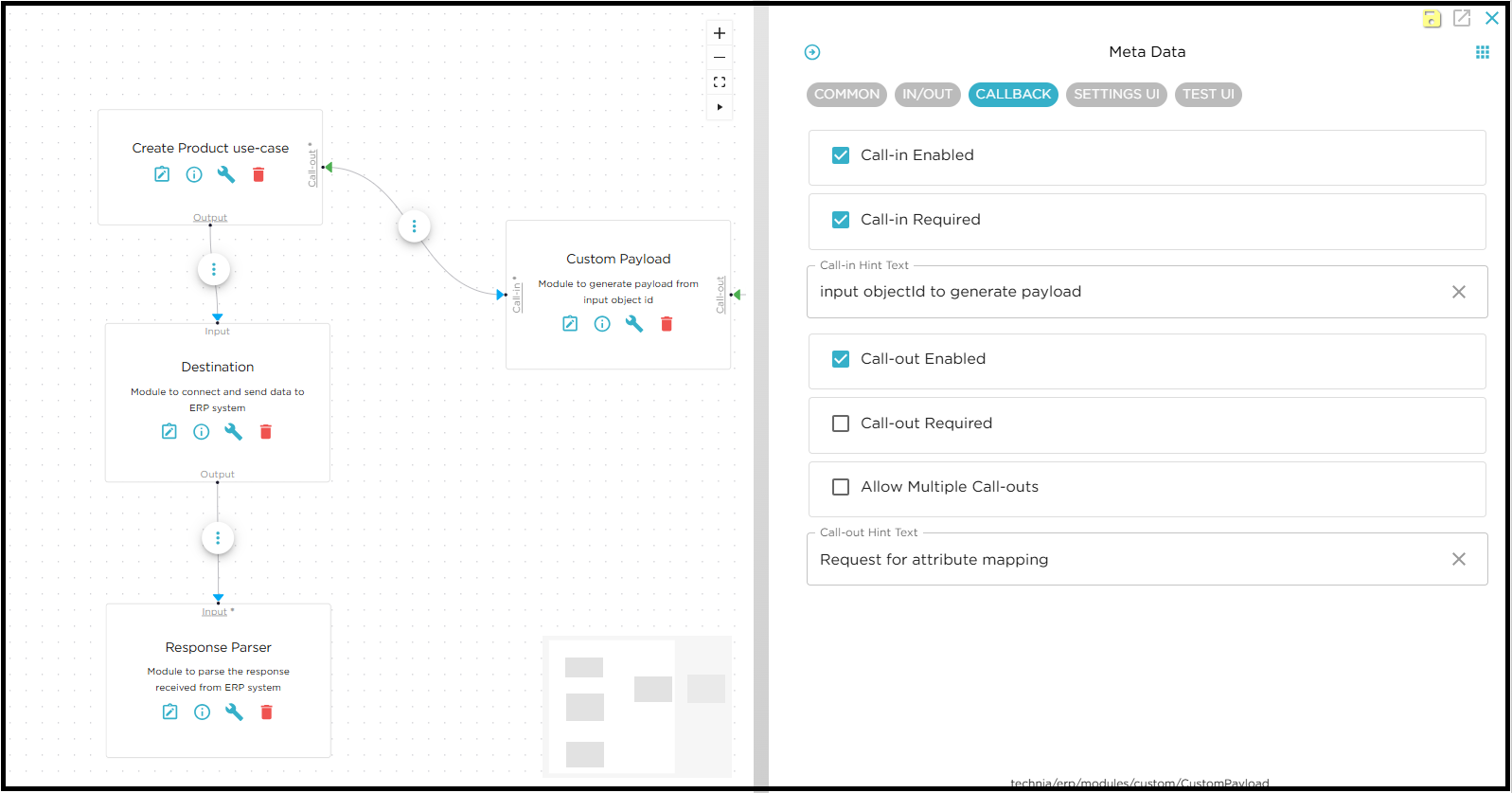
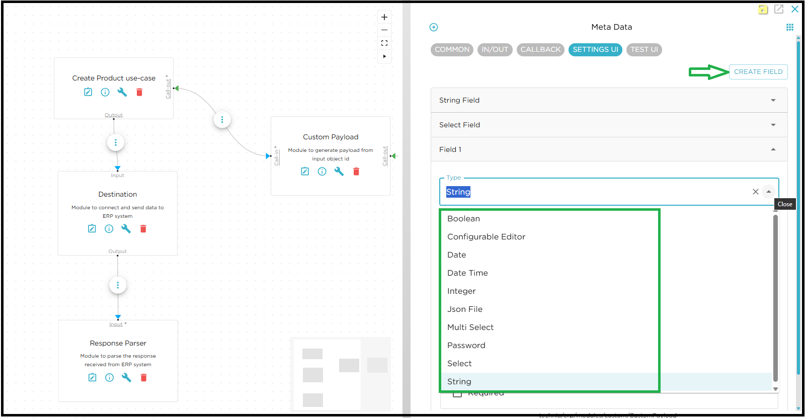
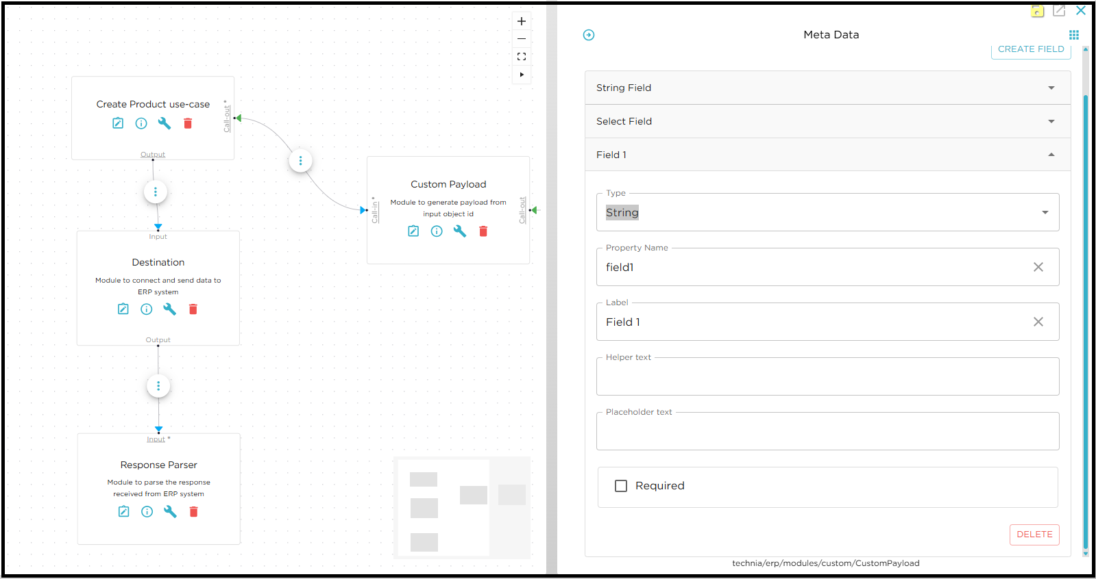
In the metadata side panel, you can configure a custom module as needed.
-
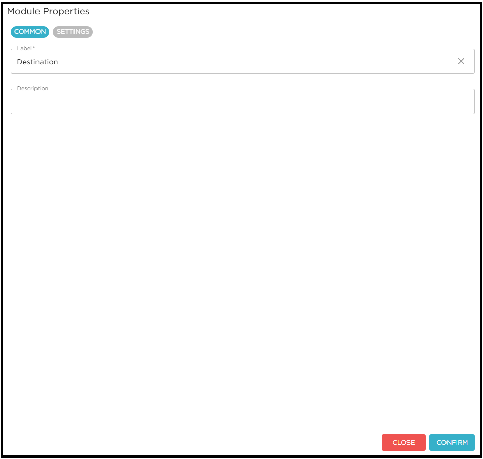
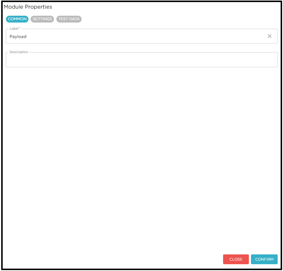
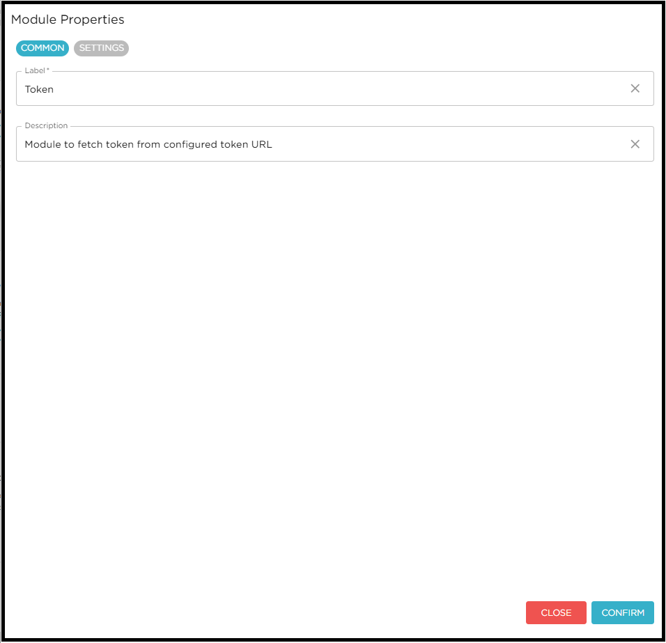
COMMON Tab: Configure the module’s label and description.
-
IN/OUT Tab: Define the module’s inputs and outputs.
-
CALLBACK Tab: Configure the module’s callback.
-
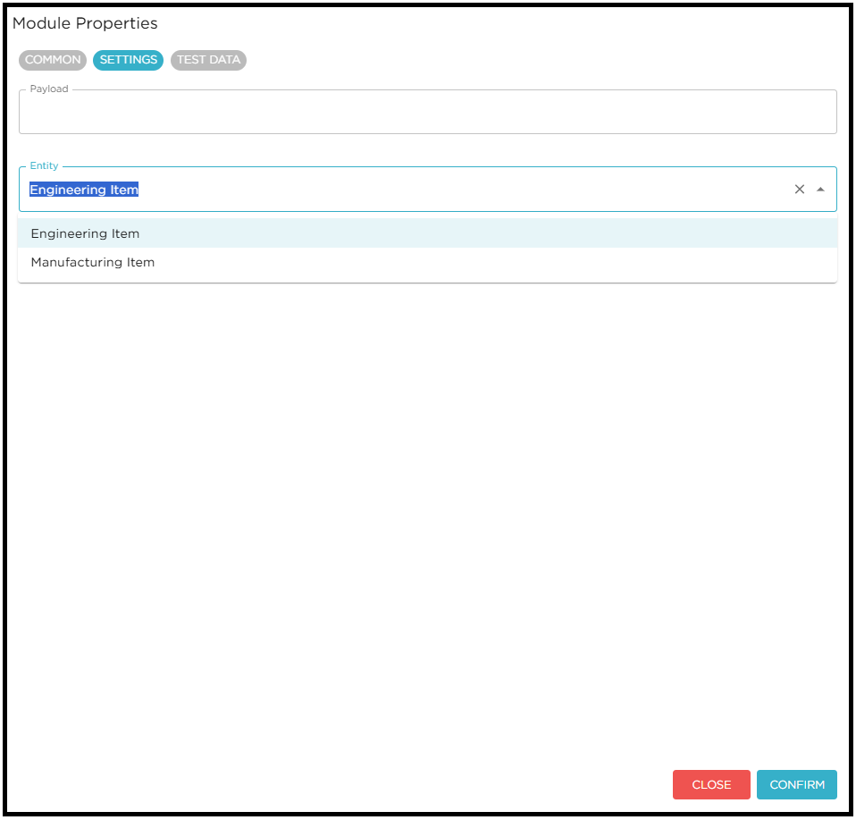
SETTINGS UI Tab: Configure the module’s properties by creating fields. The user can select the field type from the dropdown and provide the required details for field creation.
| For more details about Flow design configurations please check Flow Design Configurations |
| For more details about Flow api please check JavaScript API for Flow Modules |
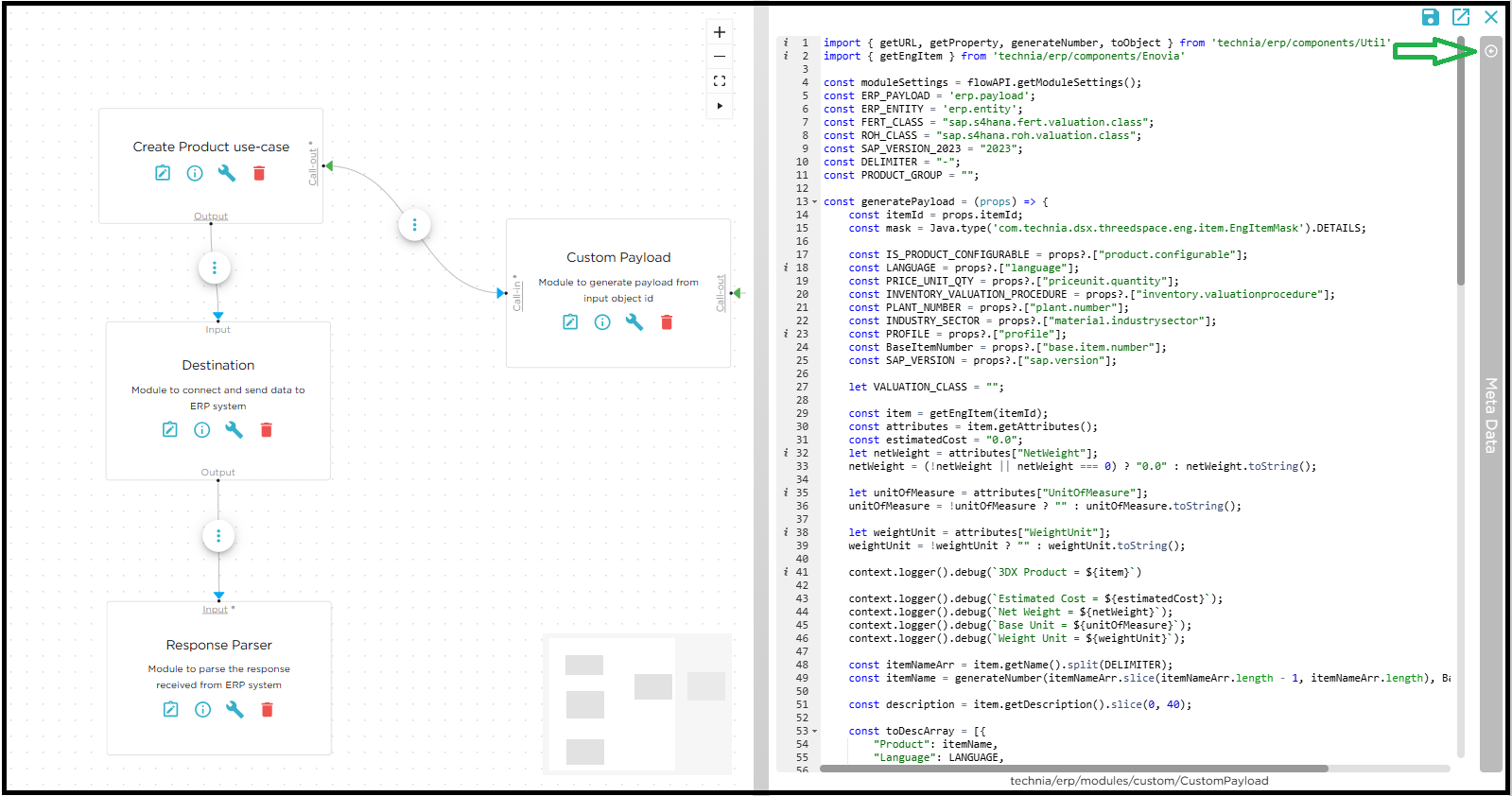
Custom Payload Module creation
-
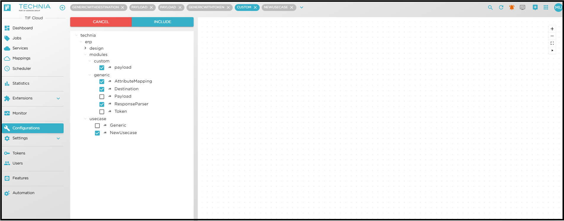
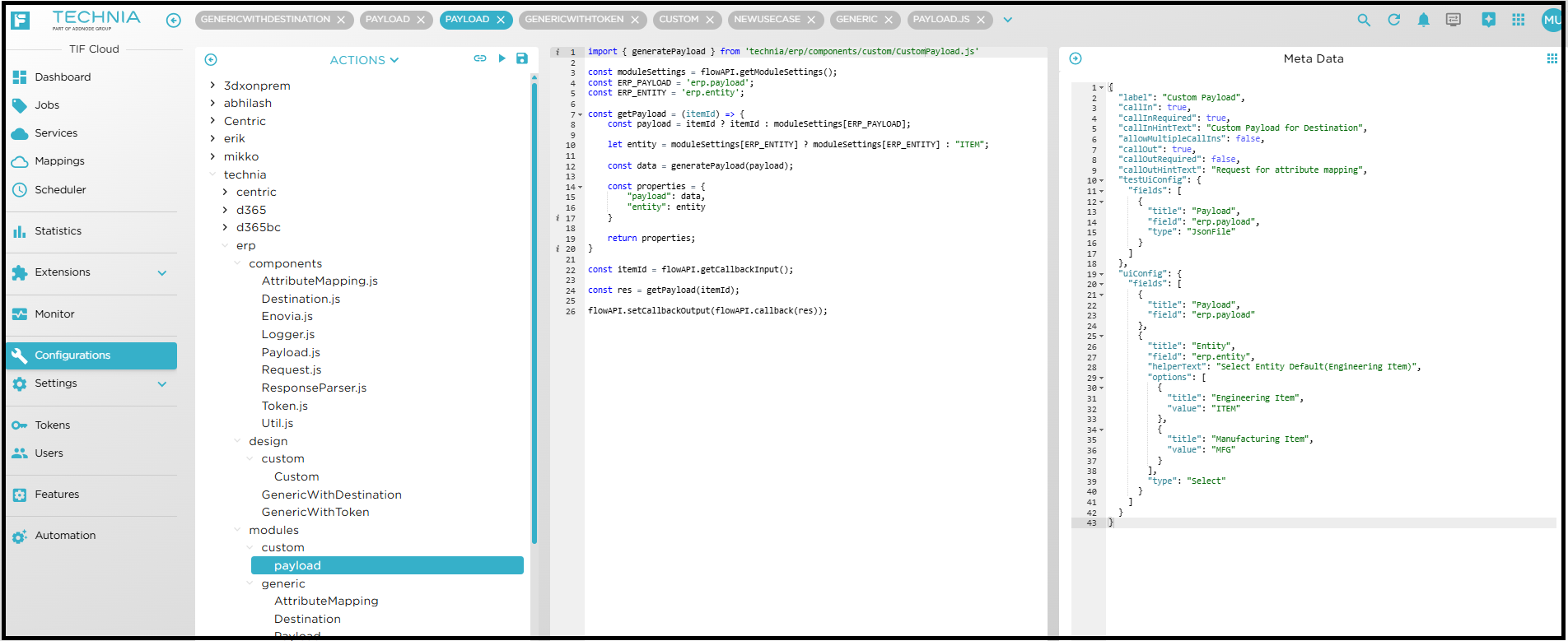
Create custom payload module and implement the functionality to generate the required payload.
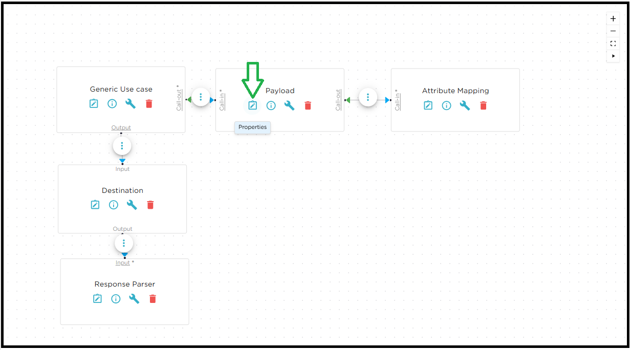
Module Configuration
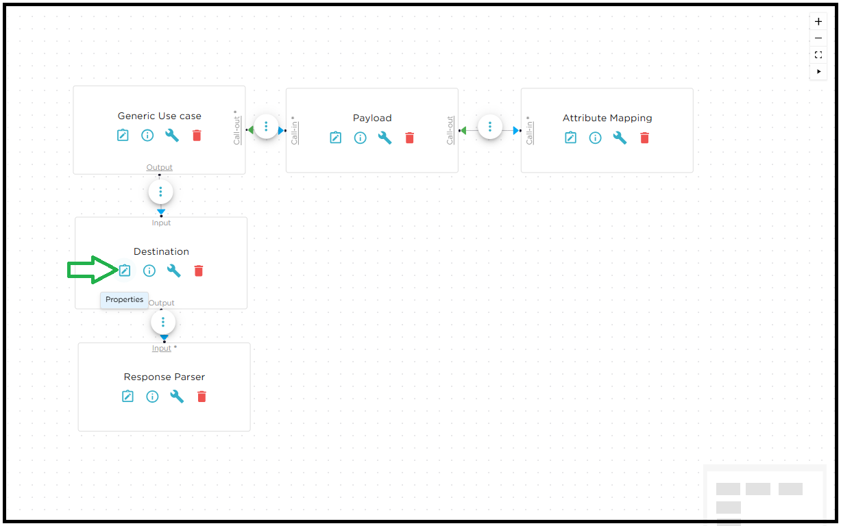
Once the design is ready, the user can configure the module properties for Destination, Payload, Attribute Mapping, and Token Module as required. The configuration options for each module are described in the following sections.
The Module Configuration settings define how modules are set up and interact with external systems. Each tab or configuration area provides specific options for customizing behaviour, managing authentication, mapping attributes, and sending data to external systems.
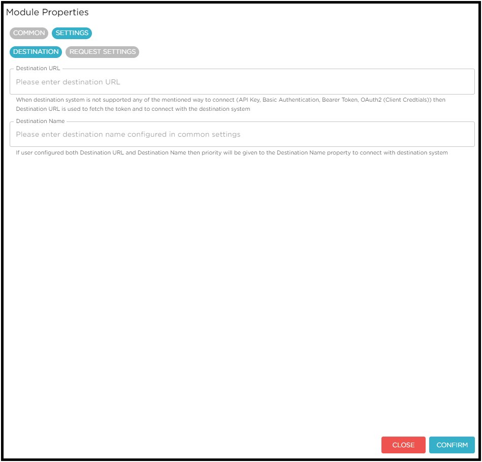
Destination Module.
The Destination Module receives the payload as input and sends it to the ERP system. The connection to the ERP system can be established using either the Destination URL or the Destination Name.
If the destination system does not support any of the standard authentication methods—API Key, Basic Authentication, Bearer Token, or OAuth2 (Client Credentials) the Token Module must be used in conjunction with the Destination Module. In this case, the Token Module is responsible for fetching the required token, which is then used by the Destination Module to connect with the destination system.
User can configure the module settings as shown below.
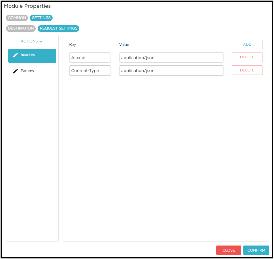
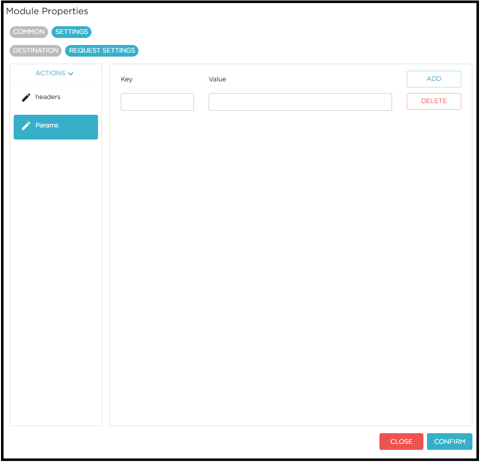
Payload Module
The Payload Module receives the Object ID as input from the Use Case Module and generates the required payload using this Object ID. The generated payload can then be sent to the Attribute Mapping Module to modify the payload according to the configured mappings.
User can configure the module settings as shown below.
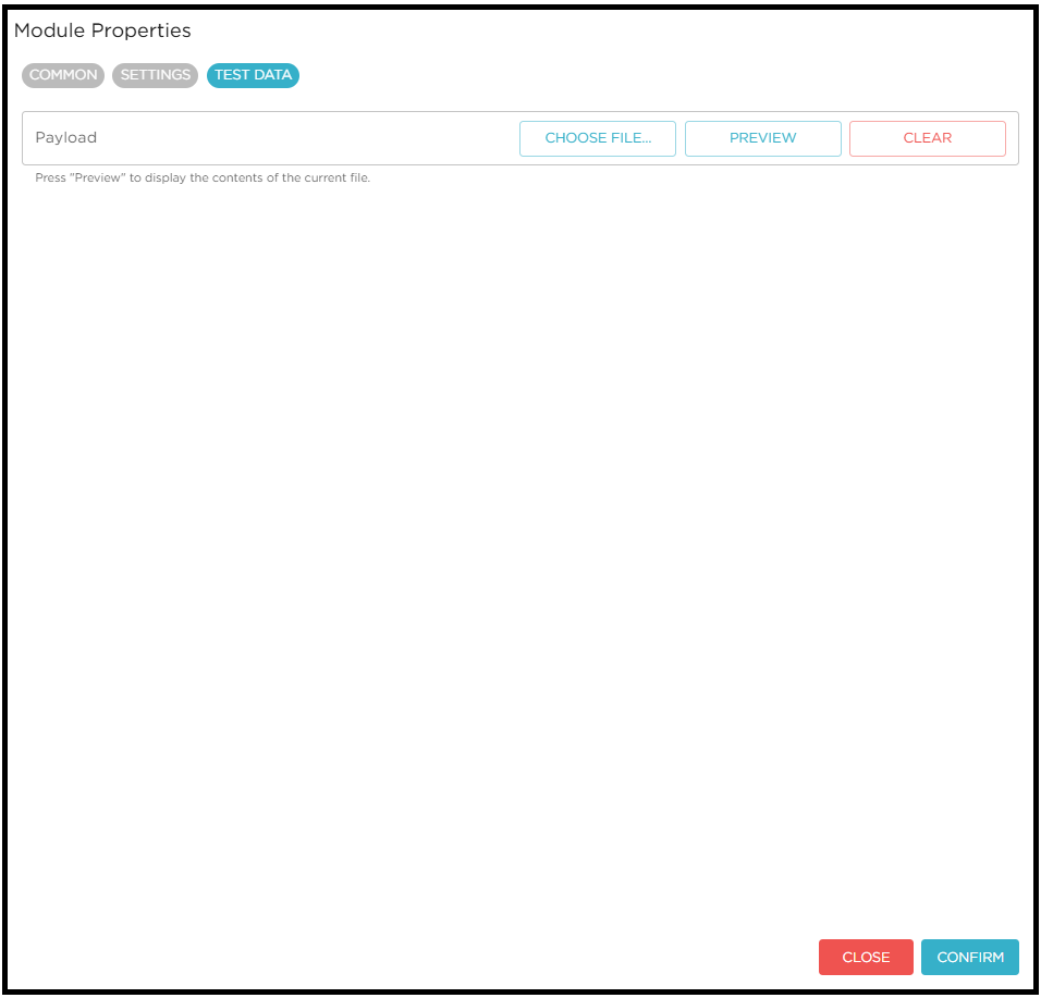
User can upload the valid payload file to test the use case design.
Supported Formats: The payload can be in any format supported by the destination system, for example, JSON or XML.
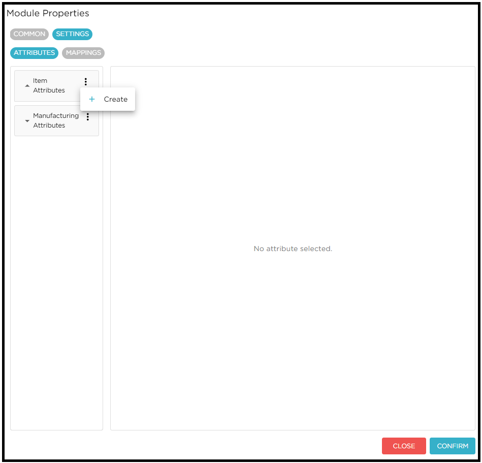
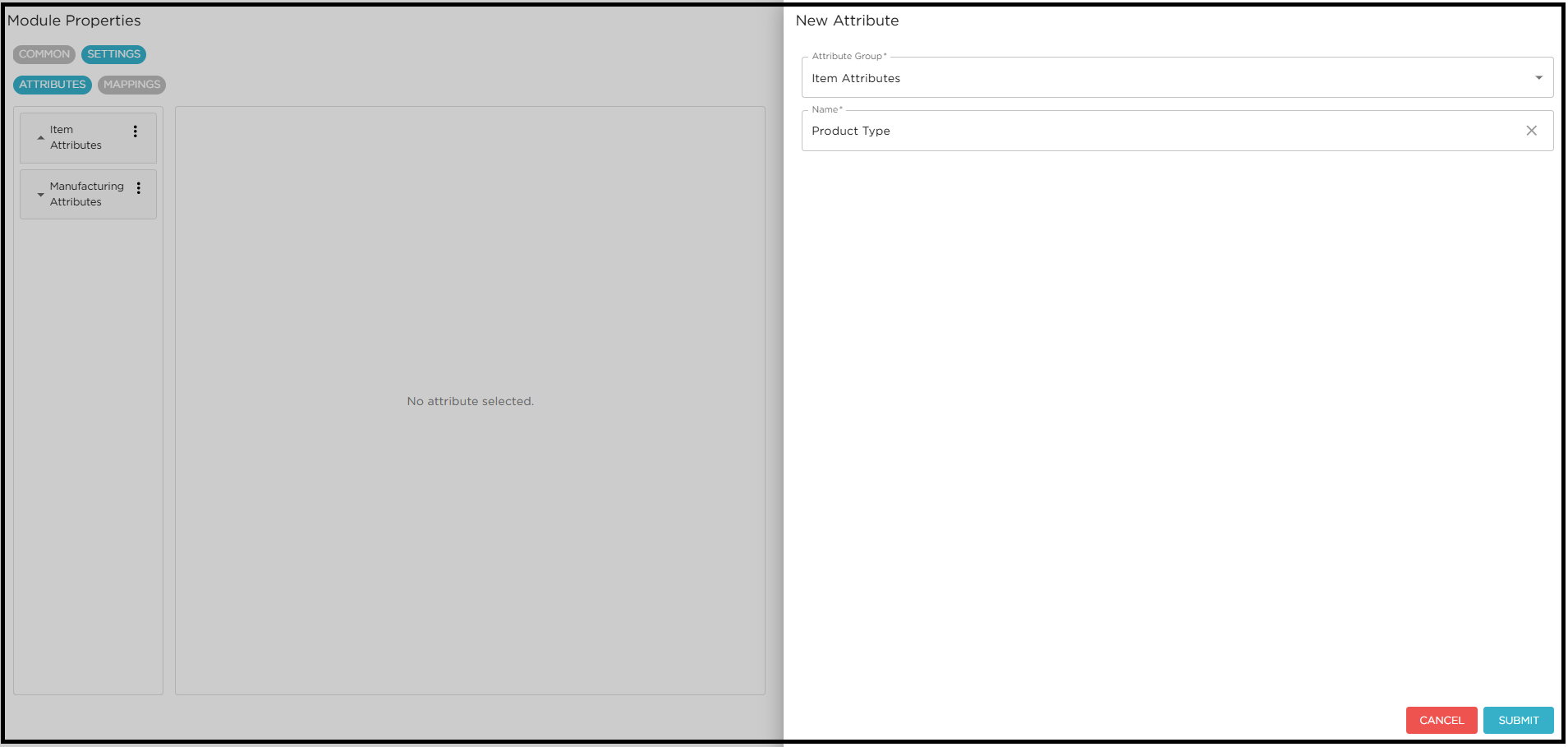
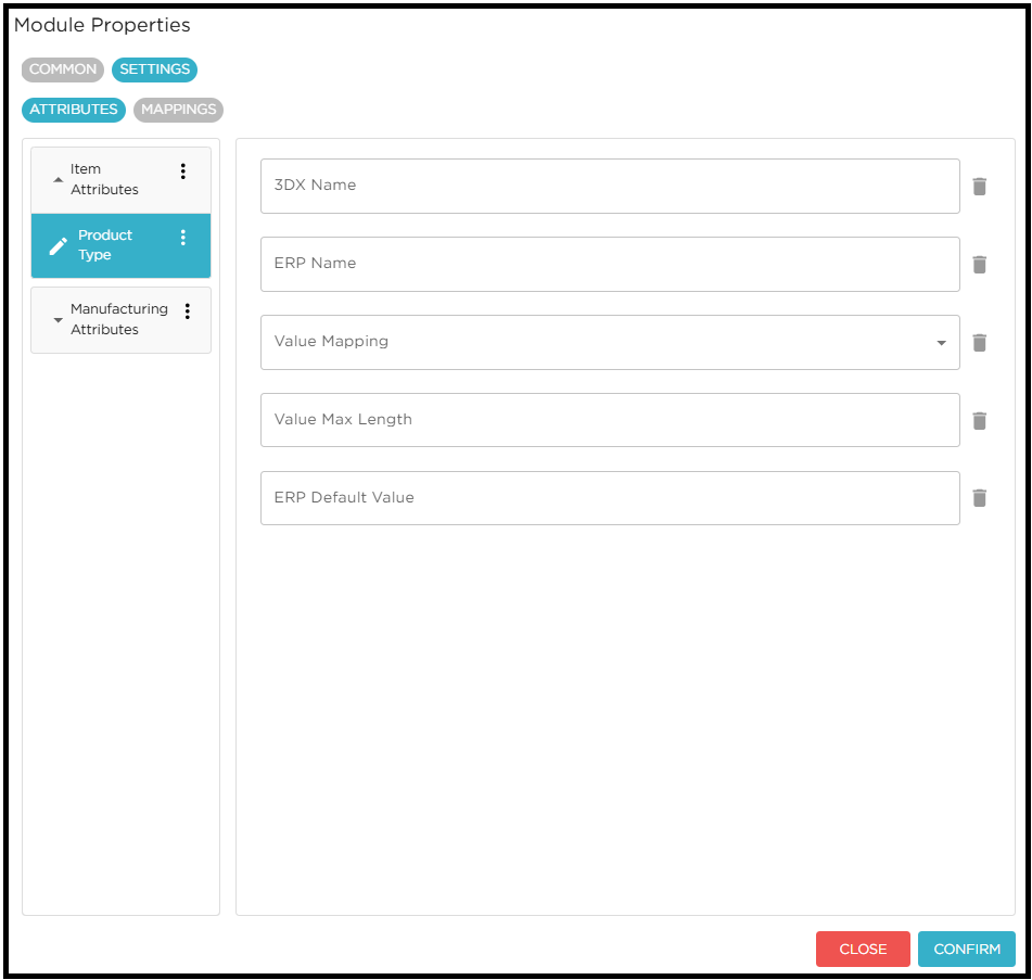
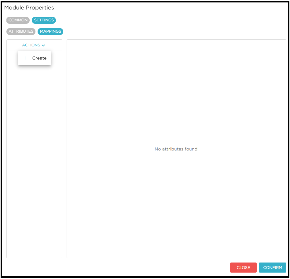
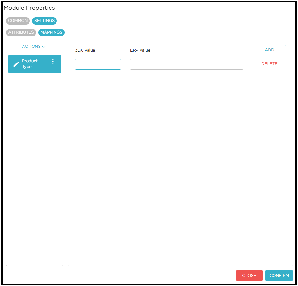
Attribute Mapping Module
Attribute mapping module helps the user to map 3DEXPERIENCE attributes with Destination attributes from UI. If there is no mapping found data will be sent as is.
User can configure the module settings as shown below.

Token Module
The Token Configuration settings are used to manage authentication when a module interacts with secured APIs. These settings define how a token is requested, which parameters are required to fetch it, and how the token or related values are read from the response and passed to other modules.
-
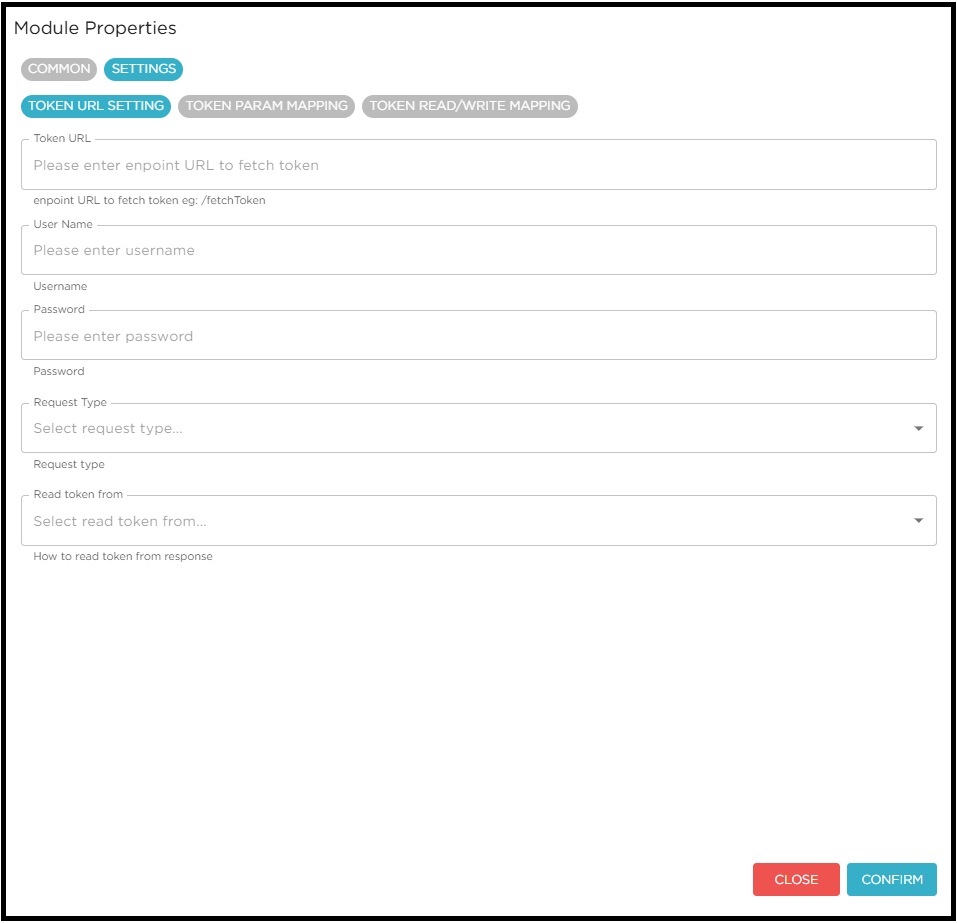
TOKEN URL SETTING
In this tab of the module settings, the user must configure the Token URL, Username, Password, Request Type, and Read Token From.
-
Read Token From: Specifies the source in the response from which the token should be read.
-
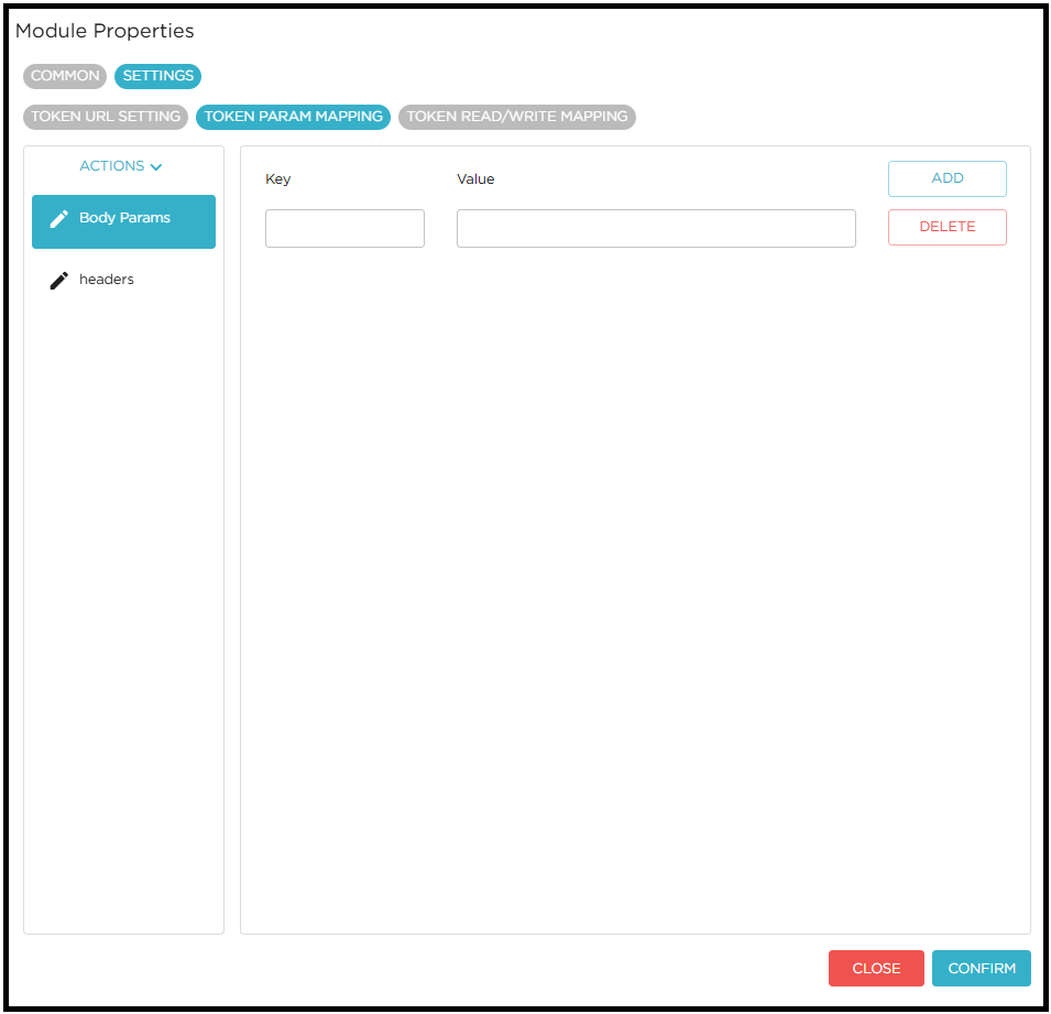
TOKEN PARAM MAPPING
In this tab of the module settings, the user can configure the required headers and parameters that will be used to fetch the token.
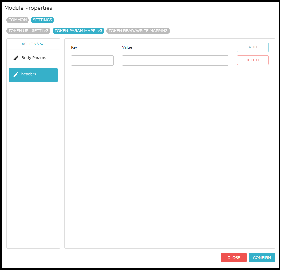
-
parameters added in the body params will be used to generate request body.
-
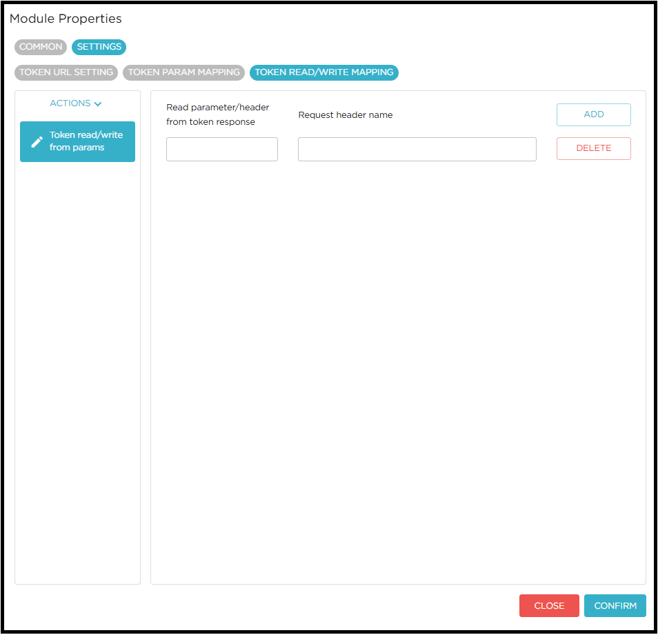
TOKEN RESPONSE MAPPING
In this tab of the module settings, the user must configure the mapping to read and write parameters from the token response.
-
Read parameter/header from token response: Defines how to read parameters from the token response.
-
Request Header Name: Specifies the header name to be used when passing the value to the Destination Module.
-
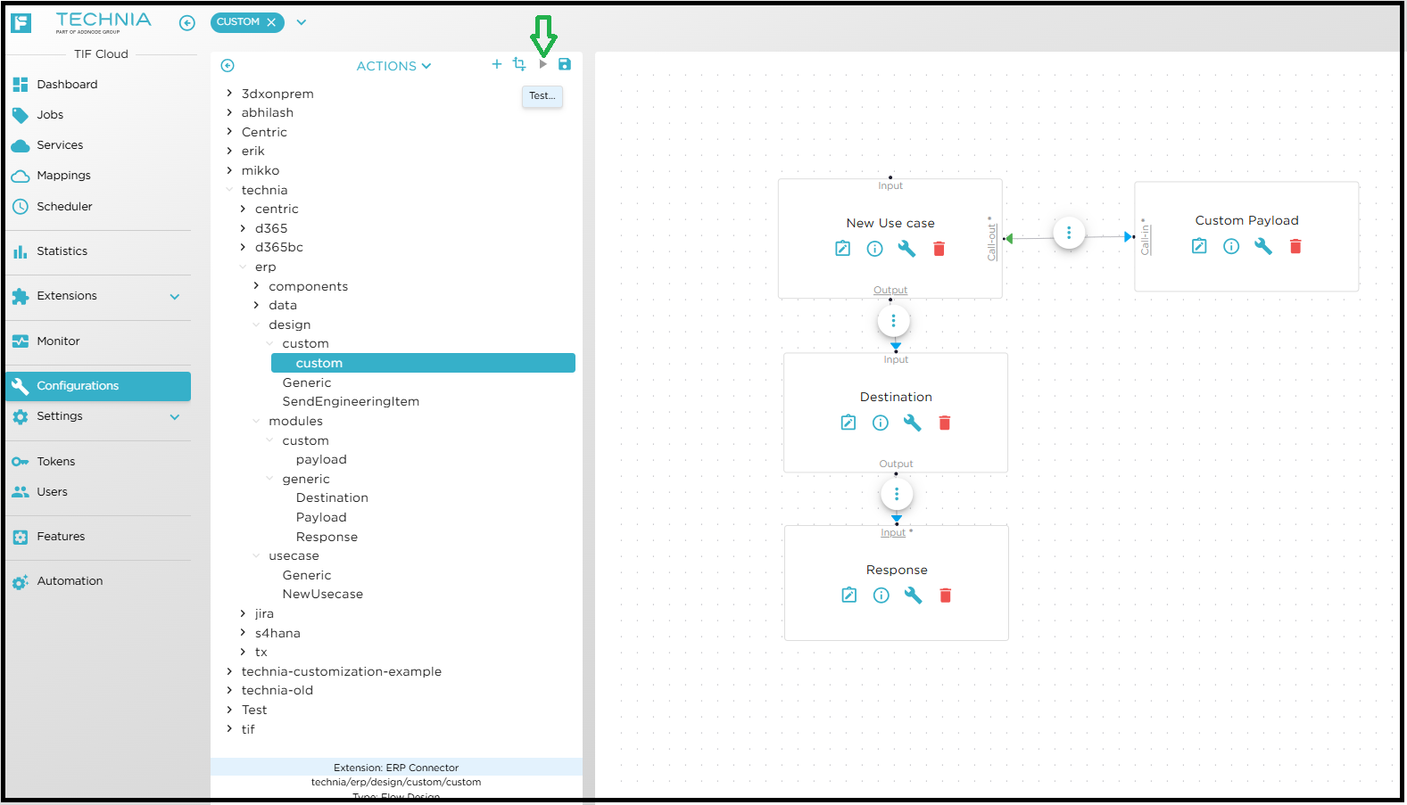
Testing the flow using the test window.
-
Open newly created custom design
-
click Test
-
The flow will execute, and the results will be displayed in the Test Window.
-
| Save the design after modifying any module configuration or setting to ensure changes are applied during execution. |
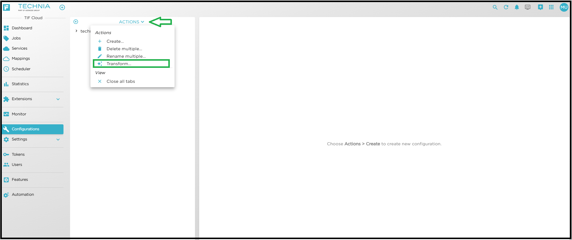
Testing a Postman collection
-
Go to Action and click on Transform to convert the postman collection into JavaScript code.
-
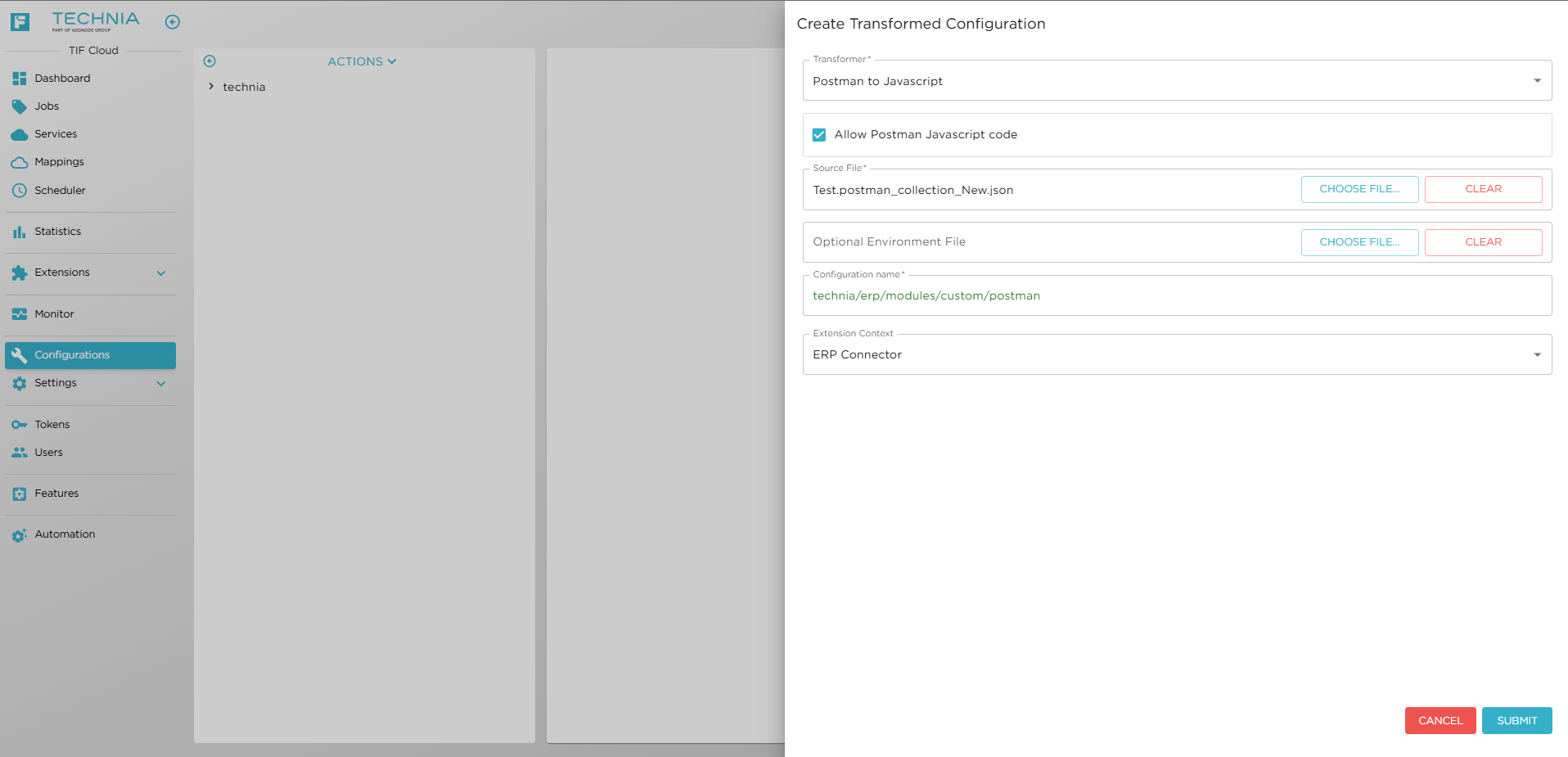
Select the Transformer.
-
Enable the Allow Postman Javascript code if you want to execute the generated Postman JavaScript code.
-
Choose the valid Postman collection file.
-
Choose valid JSON file to load environment variables.
-
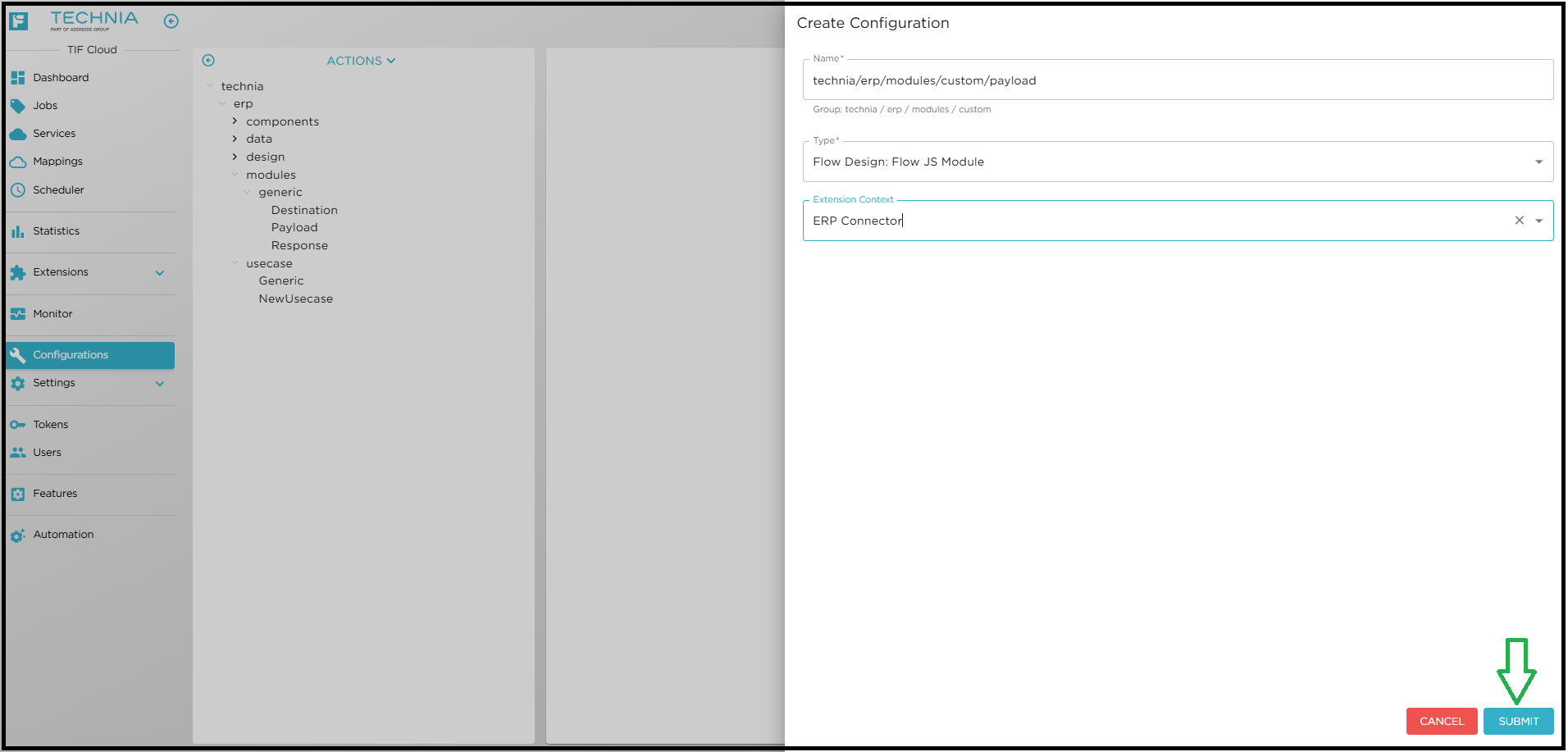
Provide the configuration location and specify a name for the configuration to be created.
-
Select Extension Context and click Submit.
-
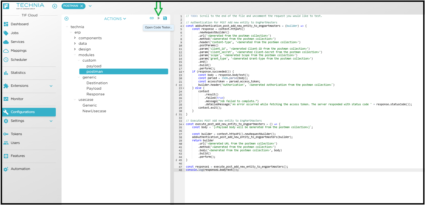
The generated configuration will open automatically.
-
Open the Test window.
-
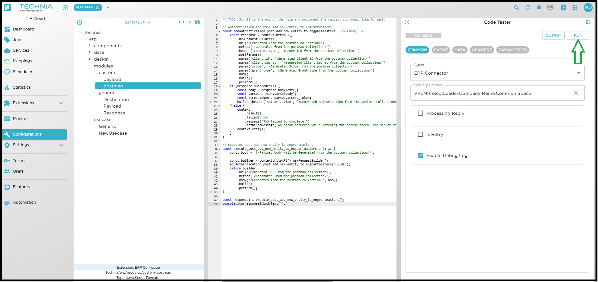
Select the Agent and provide the Security Context (If required).
-
Click RUN.
-
The execution details will be displayed in the Test Window.